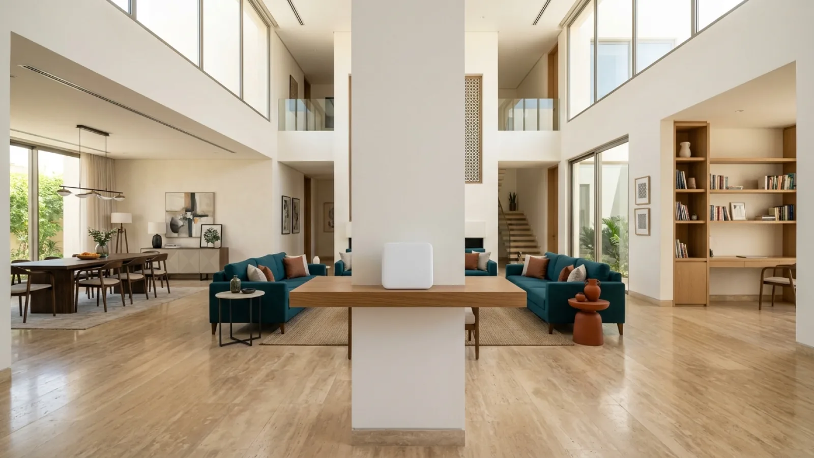

If Wi-Fi is strong near the router but weak in another room, a faster subscription may not fix it. Start with router placement, interference and home layout.
After troubleshooting, compare real Fiber and home 5G plans only if your household truly needs a change.
- Separate internet access from Wi‑Fi
- Aim for a central location
- Height and open space
- Walls, metal and interference
- Wi‑Fi bands
- Large and multi-floor homes
- Mesh, access points and FTTR
- Room-by-room testing
- When not to upgrade the plan
- Quick improvement checklist
1. Separate access from Wi‑Fi #
Test near the router or over Ethernet where practical. If the baseline is healthy but distant rooms are poor, focus on the home network first.
2. Aim for a central location #
A central position usually helps Wi‑Fi distribution. With 5G home internet, balance this against the router's radio reception from the mobile network.
3. Height and open space #
Keep the router reasonably elevated and in open space. Avoid closed cabinets and large nearby metal objects.
4. Walls, metal and interference #
Every home is architecturally unique, especially in Saudi Arabia where reinforced concrete walls, dense brickwork, and structural pillars are standard construction. Radio waves at 5 GHz and 6 GHz experience significant attenuation when traveling through solid masonry, tinted glass, mirrors, and tiled surfaces. Furthermore, proximity to large metal appliances (such as refrigerators in kitchens) or heavy electrical conduits can generate electromagnetic noise. There is no magical "wall count" formula that applies universally; empirical testing in each living space provides the only dependable truth.
5. Wi‑Fi bands #
2.4 GHz generally reaches farther through solid barriers but offers limited bandwidth and suffers heavy congestion from neighboring networks and Bluetooth devices. 5 GHz provides significantly higher data throughput and lower latency at shorter line-of-sight ranges. 6 GHz adds wider, pristine channels on compatible Wi‑Fi 6E/7 routers and client devices. Enable automated band steering when your router and devices support modern roaming protocols (802.11k/v/r), and avoid pinning client devices to specific frequencies unless dedicated testing demands it.
6. Large and multi-floor homes #
A single centralized router rarely provides uniform high-speed coverage across multi-story villas or spacious apartments exceeding 200 square meters. Before purchasing generic plug-in range extenders that cut throughput in half, map out your floor plan, note high-priority workstations and entertainment areas, and verify whether structured Cat6 Ethernet conduits are available between floors for wired backhaul.
7. Mesh, access points and FTTR #
When single-router coverage reaches its physical limit, choose the appropriate scaling architecture:
- Mesh Wi-Fi Systems: Multiple coordinated nodes that share a single network SSID and hand off devices seamlessly throughout the home.
- Dedicated Wired Access Points (APs): The gold standard for stability and speed, connecting directly to the main router via Gigabit Ethernet cabling.
- Fiber-to-the-Room (FTTR): Transparent micro-optical fiber deployed directly to individual rooms, eliminating radio attenuation entirely where FTTR packages are available.
8. Room-by-room testing #
Establish an accurate diagnostic baseline by using the same modern test device across all rooms. Test speeds and packet latency in your primary workspace, gaming zone, family living area, and remote bedrooms rather than relying exclusively on readings next to the router. Conduct separate tests during quiet daytime hours and peak evening household usage, and always measure via an Ethernet connection first to isolate ISP line speed from wireless transmission losses.
9. When not to upgrade the plan #
If internet speed tests yield 300 Mbps when standing beside your router but plummet to 15 Mbps in an upstairs bedroom, paying for a 500 Mbps or 1 Gbps fiber subscription will not resolve the bottleneck. The access link to your premises is already performing as contracted; the issue is wireless signal degradation across interior walls. Investing in router repositioning, a mesh system, or an Ethernet drop will solve the coverage deficit without inflating your monthly subscription fees.
10. Quick improvement checklist #
Review this structured action checklist to optimize your home Wi-Fi before requesting plan modifications:
- Elevate and centralize: Place the router on an open table or shelf 1 to 1.5 meters above the floor near the geometric center of your active living spaces.
- Clear immediate obstructions: Ensure at least 1 meter of clearance around the router, avoiding closed TV consoles, metal shelves, and dense cabinetry.
- Isolate access from Wi-Fi: Connect a laptop directly to the router with an Ethernet cable to verify true subscribed speed from the ONT or 5G modem.
- Audit priority rooms: Benchmark Wi-Fi signal strength and latency in work and streaming zones using dedicated speed testing tools.
- Separate interference sources: Keep the router away from microwave ovens, wireless cordless phones, power strips, and baby monitors.
- Leverage wired backhaul: Connect gaming consoles, smart TVs, and desktop PCs via Ethernet cables to preserve wireless spectrum for mobile devices.
- Deploy Mesh or FTTR systematically: If concrete walls prevent signal penetration to remote wings, install a coordinated mesh solution or FTTR rather than cheap repeating plugs.
11. 3D Radiation Patterns: Understanding Toroidal RF Propagation #
Wi-Fi signals emitted from standard residential gateways do not propagate as uniform spherical bubbles. Instead, standard dipole antennas project energy according to a precise geometric structure known as a toroidal donut pattern:
A. Physics of Omnidirectional Antennas #
- When an external router antenna is positioned vertically (90 degrees perpendicular to the floor), RF energy radiates laterally outward across a broad, horizontal disc covering the current residential floor. Crucially, a conical dead zone (the cone of silence) forms directly above and below the antenna tip.
- Placing a gateway on the floor or near baseboards directs half of the available RF power downward into reinforced concrete tiles, leaving upper floors starved of signal.
B. Optimal Antenna Alignment Across Multi-Story Properties #
For two-story villas and duplex properties seeking vertical coverage without supplementary hardware:
- Dual-Antenna Gateways: Align one antenna vertically (90 degrees) to blanket the primary floor horizontally, and tilt the secondary antenna at a 45-degree angle to project RF energy diagonally upward toward second-floor rooms.
- Quad-Antenna Gateways: Orient two antennas vertically (90 degrees) and cant two antennas at 45 degrees in orthogonal directions, generating a three-dimensional radiation envelope that penetrates vertical stairwells and upper halls.
12. Structural RF Attenuation Across Saudi Building Materials #
Saudi residential architecture relies heavily on high-density structural concrete and thermal masonry, presenting severe physical insertion loss to radio frequency propagation:
| Architectural Material / Interior Barrier | 2.4 GHz Attenuation (dB Loss) | 5 GHz Attenuation (dB Loss) | Practical Impact on Connected Devices |
| :--- | :--- | :--- | :--- |
| Interior Drywall & Hollow Wood Doors | 2 to 3 dB | 3 to 5 dB | Negligible; easily traversed by 5 GHz |
| Hollow Red Clay Brickwork | 4 to 6 dB | 7 to 10 dB | Moderate; reduces throughput by 20–30% |
| Dense Concrete Blocks & Thermal Insulation| 10 to 14 dB | 16 to 22 dB | Severe; frequently extinguishes 5 GHz |
| Double-Reinforced Structural Concrete | 18 to 25 dB | 25 to 35 dB | Impenetrable; zero 5 GHz traversal |
| Large Mirrored Panels & Low-E Glazing | 8 to 12 dB | 14 to 20 dB | Silver backing reflects RF waves completely |
Definitive Engineering Takeaway: #
Never position a primary gateway inside an enclosed alcove bounded by reinforced concrete load-bearing walls. Direct line-of-sight propagation through open doorways and corridors provides ten times greater signal strength than attempting to blast RF energy through structural concrete columns.
13. Channel Planning and Co-Channel Interference Mitigation #
In high-density apartment communities across Riyadh and Jeddah, dozens of domestic gateways broadcast over identical frequency bands, inducing acute co-channel interference and latency spikes:
A. Non-Overlapping Channels in the 2.4 GHz Spectrum (1, 6, and 11) #
- The legacy 2.4 GHz spectrum provides only three physically non-overlapping channels: 1, 6, and 11.
- Configuring a gateway to an intermediate channel (such as 3, 4, or 8) induces adjacent-channel interference across both sides of the spectrum, forcing all nearby routers to back off packet transmissions and crashing data rates below 10 Mbps.
B. Channel Width Optimization on the 5 GHz Band (80 MHz vs 160 MHz) #
- A 160 MHz channel width delivers theoretical gigabit links for Wi-Fi 6 clients, but spans the entire 5 GHz spectrum and triggers frequent DFS radar back-off disconnections near airports and meteorological stations.
- In dense urban environments, locking channel width to 80 MHz provides an optimal balance: robust DFS immunity, low background noise, and sustained real-world throughput exceeding 700 to 800 Mbps.
14. Architectural Comparison of Coverage Extension Topologies #
When a standalone gateway cannot cover an expansive floor plan, four architectural extension methodologies exist:
1. Simple Plug-In Wi-Fi Repeaters #
- Engineering Verdict: Strongly Discouraged.
- Cheap repeaters receive a degraded wireless signal and rebroadcast it over the same half-duplex radio, instantly halving throughput and doubling ping times while lacking 802.11k/v/r seamless roaming protocols.
2. Tri-Band Wireless Mesh Systems #
- Engineering Verdict: Acceptable for Medium Apartments.
- Uses a dedicated wireless backhaul radio. However, inter-node backhaul links remain vulnerable to concrete wall attenuation, losing 30% to 50% capacity across thermal partitions.
3. Ethernet Backhaul Mesh Infrastructure #
- Engineering Verdict: The Gold Standard for Modern Villas.
- Interlinks satellite mesh nodes via structured Cat6 Ethernet cabling back to the core switch. Every access point delivers dedicated, unshared gigabit throughput with sub-millisecond local latency and seamless client handoffs.
4. Transparent Fiber-to-the-Room (FTTR) #
- Engineering Verdict: The Ultimate Premium Pipeline.
- Replaces copper cabling with ultra-thin, invisible optical fibers routed to every room. Each floor hosts a dedicated Sub-ONT emitting pure optical-speed Wi-Fi 6/7 with zero latency compromise.
15. Standardized Heatmap Survey Protocol for Identifying Dead Zones #
Before investing in supplementary hardware, execute this structured RF site audit utilizing mobile Wi-Fi diagnostic applications:
A. Deciphering Real-World RSSI Signal Metrics #
Received Signal Strength Indicator (RSSI) is expressed as negative dBm values, where numbers closer to zero indicate stronger signal power:
- Optimal (-30 to -50 dBm): Direct line-of-sight proximity; maximum modulation rates and sub-2 ms local latency.
- Very Good (-51 to -65 dBm): Standard healthy baseline for adjacent rooms; flawless 4K streaming and competitive gaming.
- Marginal (-66 to -72 dBm): Throughput begins to taper, though voice calls and basic browsing remain operational.
- Degraded (-73 to -80 dBm): Frequent packet drops, severe video buffering, and elevated jitter.
- Dead Zone (Below -82 dBm): Total connection failure and packet timeouts.
B. Five-Point Domestic Walkthrough Routine #
- Gateway Demarcation Baseline: Verify that mobile clients register -35 dBm on the 5 GHz band adjacent to the router.
- Primary Living and Entertaining Zones: Confirm signal power remains superior to -60 dBm.
- Closed-Door Bedrooms and Private Suites: Measure signal loss through timber doors and masonry partitions.
- Kitchen and Wet Utilities: Note RF reflection around metallic refrigerators, ovens, and plumbing risers.
- Exterior Majlis and Garden Patios: Establish the physical boundary where signals decay below -75 dBm to position mesh nodes accurately.
Conclusion #
Home Wi‑Fi design is part of internet quality. Improve placement and distribution before paying for more access capacity that may never reach the rooms that need it.
Internal links #
/support · /coverage · K11 · K15 · K16 · K17 · K19
Editorial source review #
Review current Wi‑Fi Alliance terminology and the capabilities of the actual governed router/equipment before making device-specific claims.
Plan Wi-Fi Placement Before Buying More Hardware #
Start with the router itself. Placing it inside a cabinet, behind a television, on the floor or next to a large metal surface reduces the chance of good distribution. Aim for a relatively elevated, open position near the center of the main usage area. No placement is perfect for every home, but removing obvious obstacles often improves coverage before any new hardware is purchased.
Divide the home into usage zones rather than room names alone. Work, television, gaming and sleeping areas have different priorities. Walk through them with a phone or laptop and record connection quality and practical performance. If the drop consistently begins after a particular wall or corridor, you now have evidence for where an access point or mesh node may help.
Do not place an extender inside the dead zone itself. An extender must first receive a usable signal before repeating it. If it sits where the network is already weak, it simply rebroadcasts a weak link. A point between the router and problem area is usually more useful. Ethernet backhaul is stronger still because the access point no longer depends on a wireless inter-node link.
Treat 2.4, 5 and 6 GHz as different tools. Higher frequencies can provide more capacity in suitable conditions but generally penetrate obstacles less effectively. Do not force every device onto one band. Distant or simple devices may work well on 2.4 GHz, while nearby high-performance devices can benefit from 5 or 6 GHz when supported by both router and client.
Channel congestion can produce strong signal bars but disappointing performance. Dense apartment buildings may contain many overlapping networks. Some systems select channels automatically, but practical results matter most: do calls stutter, does latency rise on Wi-Fi and return to normal over Ethernet, or does performance collapse only at certain times? Those comparisons expose wireless-medium problems.
Fixed devices that need consistency are good Ethernet candidates: a gaming system, work computer, television or access point. Every fixed device moved onto a cable reduces demand on shared radio airtime and leaves more capacity for phones and portable devices. You do not need to wire the entire property; one strategic cable can materially improve the network.
Mesh does not automatically mean higher speed. Its main value is more consistent coverage and smoother movement between nodes. If the backhaul between nodes is weak, real performance can disappoint. Position each node where it can maintain a strong upstream link, or use Ethernet backhaul when practical.
After every placement change, repeat the same tests from the same locations at a similar time. Do not rely on impression alone. Record before and after: approximate throughput, latency, call or stream stability and connection quality in the problem room. A useful improvement solves the target problem without creating a new weak area elsewhere.
| Decision field | Practical question | What to record |
|---|---|---|
| Usage | What happens at peak time? | Simultaneous devices and workloads |
| Measurement | Is the result consistent? | Download, upload, latency and notes |
| Coverage | Does the address qualify? | State, date and source context |
| Cost | What is the full cost? | VAT, equipment, commitment, promo expiry |
| Home network | Is the bottleneck inside the home? | Wired vs Wi-Fi and router position |
The order to try before buying mesh #
Make changes in sequence: raise the router into an open position, move it away from metal and obvious interference sources, retest the important rooms, then try a different band or channel when the system allows it. Only after those steps should you evaluate mesh or an additional access point. This order avoids buying extra hardware when the underlying problem is simply poor router placement.
If you do add a node, test its location before making it permanent. A node with weak backhaul repeats the problem rather than solving it. Measure not only throughput but latency and stability during a call or stream. In a multi-floor home, one wired access point between floors can be more effective than several wireless extenders that all depend on the same weak upstream link.
Change one variable at a time #
If you move the router, change channels and add mesh on the same day, you will not know which action solved the problem. Change one variable, test, then move to the next step. This takes a little longer but prevents unnecessary hardware purchases and gives you a clear map of what actually affects the home network.